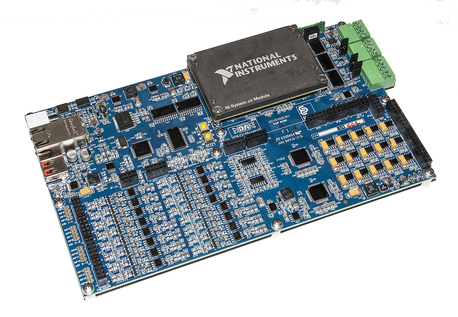
– PED-Board concept –
A dedicated board having the specific features that cover the requirements of the Power Electronics and Drives (PED) applications. Accordingly, the PED-Board has been designed and realized to exploit the benefits of the NI SoM (formally sbRIO-9651) and LabVIEW graphical programming. PED-Board incorporates ADC, DAC, CAN-bus and many other functionalities that can cover the requirements of a typical PED project.
Proposed PED-Board can be connected to almost every power converter thanks to the application specific Adapter Board. The Adapter Board is placed on top the PED-Board providing mainly the required connections to the outer world.
PED-Board is the right companion for the so called software-defined PED application
One board, specific software…a world of possibilities
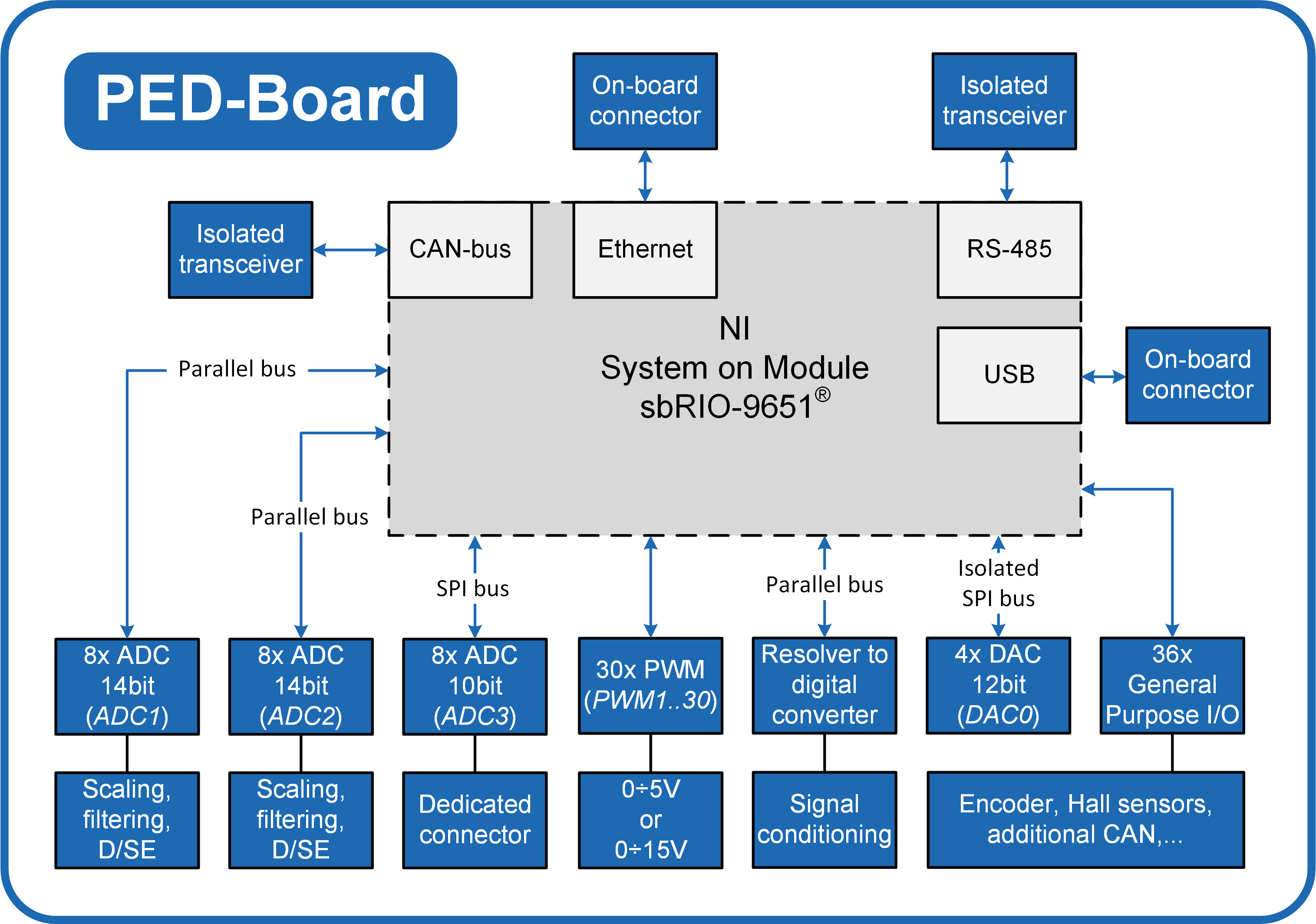
FUNCTIONAL BLOCK DIAGRAM
FEATURES
30 x PWM channels
- 0÷15 V or 0÷5V selectable voltage swing
- Direct LED driving capability for optocoupled gate driver
- Additional PWM channels available through the Digital I/O interface
14-bit ADC, 8 Channels
- Simultaneous sampling
- 1.45 μs conversion time, 8 channels
- Differential or single-ended input (each channel)
- Configurable scaling circuit (each channel)
- Second order low-pass Butterworth active filter with
configurable cut-off frequency
14-bit ADC, 8 Channels
- Simultaneous sampling
- 1.45 μs conversion time, 8 channels
- Differential or single-ended input (each channel)
- Configurable scaling circuit (each channel)
- First order low-pass Butterworth active filter with configurable
cut-off frequency and impedance matching circuit
10-bit ADC, 8 Channels
- Up to 200 kS/s
12-bit DAC, 4 Channels
- Digital-to-analog converter with 10 μs settling-time
- Isolated, no ground loops
Resolver interface
- Fully configurable electrical interface
- Speed and position measurement
- Resolver fault detection
36 x Digital I/O
- Hall-effect position sensors interface
- Encoder interface
- Relay control
- Additional PWM
- General purpose I/O
1 x 10/100/1000 base-T Ethernet port
- Auto-negotiated, half/full-duplex
- Programming, debugging and operation
1 x RS-485
- Isolated transceiver
- Half-duplex and full-duplex communication
- On-board terminator resistor
1 x CAN-bus
- 2.0A and 2.0B support, up to 1 Mbit/s
- Isolated transceiver
- On-board terminator resistor
USB port
Concluding, proposed PED-Board can be certainly used in the fields of Power Electronics and Electrical Drives as main control board. It integrates on the same platform low-level high-speed control features on the FPGA; whereas complex tuning or control algorithms, main communication interfaces and web services can be located on the Real-Time target (CAN-bus, RS-485, Ethernet; Linux OS).