 Important notice: Adapter board for Skiip3 power module must be used at least with the released PED-Board CLIP_8, when used with the PED-Board V1. (download)
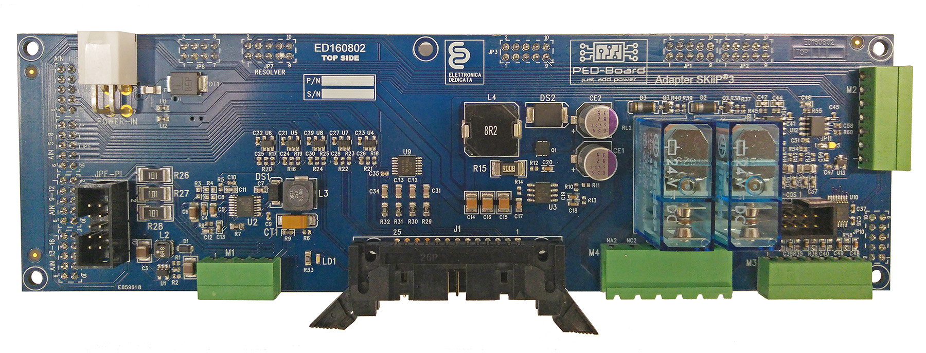
Main information
- Main power supply 12V, same PED-Board connector and pinout
- Connector for High Voltage Sensing Board (HVSB V1 or V2) for 3 independent and isolated voltage measurements (JPF-PI)
- On-board power supply for Skiip intelligent power module
- Resolver port
- Incremental encoder interface
- Sin/Cos position sensor (on-board configurable level shifter)
- Connector for additional 3 external measures with +-15V power supply and on-board resistor for current-to-voltage conversion (differential or single-ended inputs)
Pin routing
- Skiip DC-link voltage – PED-Board AIN7 (LSB=83.6mV/bit)
- Skiip Temp – PED-Board AIN8 (LSB=14.22m°C/bit with linear approximation)
- Skiip currents Ia, Ib, Ic – PED-Board AIN4, AIN5, AIN6 (LSB=79.98mA/bit)
- High Voltage Sensing Board (HVSB) – PED-Board AIN1, AIN2, AIN3
- External measures Ex1, Ex2, Ex3 : PED-Board AIN9, AIN10, AIN11
- Skiip phase A switch TOP/BOTTOM – PED-Board PWM21/PWM22
- Skiip phase B switch TOP/BOTTOM- PED-Board PWM23/PWM24
- Skiip phase C switch TOP/BOTTOM – PED-Board PWM25/PWM26
- Skiip ERROR HB-A – PED-Board I/O_0
- Skiip ERROR HB-B – PED-Board I/O_1
- Skiip ERROR HB-C – PED-Board I/O_2
- Skiip OV TEMP – PED-Board I/O_3
Connectors
1 – Sin-H
2 – Sin-L
3 – Cos-H
4 – Cos-L
5 – Carrier-H
6 – Carrier-L
7 – Shield
1 – 5V power supply, max 150mA
7 – Power supply GND
All pins can be configured as input or output. 5V logic. Refer to TXB0106PWR for detailed characteristics.
2 Digital I/O – PED-Board I/O_10
3 Digital I/O – PED-Board I/O_9
4 Digital I/O – PED-Board I/O_8
5 Digital I/O – PED-Board I/O_7
6 Digital I/O – PED-Board I/O_6
1/2 R+/R- – PED-Board AIN-14
3/4 B+/B- – PED-Board AIN-13
5/6 A+/A- – PED-Board AIN-12
7 – 5V supply, max 150mA
8 – Power supply GND
M1 pinout (External measures)
Each external measure is connected to a 100 Ohms resistors for current to voltage conversion.
1 – +15V power supply, max 400 mA
2 – External measure routed to AIN-9 (R26)
3 – External measure routed to AIN-10 (R27)
4 – External measure routed to AIN-11 (R28)
5 – -15V power supply, max 400mA
M4 pinout (2x Relay)
M4 connector is dedicated to a SPDT relay system. Two independent relays with NO or NC configuration.
Relay1 is controlled by PED-Board I/O_5, whereas Relay2 by I/O_4. H-value triggers the relay.
1 – Relay1 center tap
2 – Relay1 normally closed (NC)
3 – Relay1 normally open (NO)
4 – Relay2 center tap
5 – Relay2 normally closed (NC)
6 – Relay2 normally open (NO)
